Delivery and Returns
Free Delivery
Conditions:
- Orders must be over £150 + vat*
- Excludes batteries and other palletised orders
- Delivery covers most of mainland England and Wales but excludes Scotland, Highland and Islands. These areas will incur a charge.
- Delivery is from date of item being in stock
- Only available on web orders
- We can not take any responsibility for delays in delivery due to courier changes or exceptional circumstances.
AM Delivery Option
We offer a chargeable AM Delivery option for orders placed before 1pm Monday-Friday (excluding Bank Holidays). The charges for this will be applied in your basket and are based on weight of the order and destination address.
Collect In Person
We are happy for you to collect your order from our head office if that is more convenient. Please indicate this on your order and we will hold your order here for you.
International Delivery
We can deliver goods to many international destinations. Please be aware that costs shown for international orders do not include local taxes and duties - these will be payable by the importer at the time of import into the country.
Order Tracking
You can track the status of your order on-line in the Account section of the site. This will show you when your order has been despatched - it will be flagged as "completed", you will also receive an email when the goods are despatched, If an order is showing as "pending" it may be that part of the order has been despatched and the rest is on back order, or the whole order is waiting to be despatched.
Returns
We are happy to undertake returns as per our terms and conditions. Please ensure however that you study the technical information for each product carefully as we can only offer an exchange if the item is faulty. Returns will only be accepted if a completed returns form is submitted.
Warranty Repairs
Free repairs are offered on faulty goods within warranty. Outside of warranty, the unit will be repaired/replaced at the relevant cost; all prices will be quoted before work is carried out.
Terms & Conditions
Please note images used on the ES Store site are for illustration purposes only and do not necessarily show the actual model being described. Please read our full terms and conditions before placing your order.
Frequently Asked Questions

What types of batteries does Energy Solutions offer for sale?
Energy Solutions offers a wide range of batteries, including lead-acid, lithium-ion, deep-cycle, and more. Our inventory includes batteries suitable for various applications, from automotive to renewable energy systems.
Do you provide any warranty or guarantee on the batteries you sell?
Yes, we stand behind the quality of our batteries. Energy Solutions offers warranties or guarantees on our products to ensure customer satisfaction. The specific warranty terms may vary depending on the battery type and brand.
Can I get assistance in selecting the right battery for my specific needs?
Absolutely! At Energy Solutions, we have knowledgeable staff ready to assist you in choosing the right battery for your requirements. Whether it's for a car, boat, solar power system, or any other application, we can provide expert guidance to ensure you get the best battery solution.
EasyGrid
Can the EasyGrid be kept outside?
Yes, the Zinc powder coated steel enclosure is weatherproof, however many clients choose to house the unit in an outbuilding.
How many solar panels can I have connected?
Standard for all our EasyGrids is 4kW of solar panels. You can increase the size of this solar array by upgrading the EasyGrid.
Can I add solar at a later date?
Yes, the EasyGrid is pre-wired and ready to accept up to a 4kw solar array, this can be added when this best suits you.
Can I add a wind turbine as well as solar panels?
Yes. All of the EasyGrids can be upgraded to include the dump load and flight controller wired inside the unit, so your wind turbine is all ready to connect on site.
Can I connect an EasyGrid to my existing generator?
Yes, if you already have an auto-start generator that is a suitable size you can use this with the EasyGrid.
I own a 3 phase generator.an I use this for the EasyGrid?
Yes , you can buy an EasyGrid upgrade which allows 3 phase generators to be connected.
Do I have to use a generator?
No, not necessarily. If you have enough renewable energy sources and can get a good return from these in comparison to your loads, it is possible to be able to run the system without the use of a generator.
Do you (Energy Solutions) install the whole system?
We can give you a quotation for installing and commissioning your system, however as the system is so simple customers can have a local qualified electrician install it.
How long will it take to install?
Installation is very quick, and can be completed inside of a day.
Is the EasyGrid noisy?
The EasyGrid unit itself is completely silent.
How often will my generator run?
This all depends on how frequent your peak loads are and the use within the property. The EasyGrid will only ever run the generator when the loads go above the inverter capacity or the batteries are depleted to 50% discharge.
Will an EasyGrid system start my generator during the middle of the night?
No, the EasyGrid will run off battery power if loads are low at night, so you will have silent power during the night.

What is Victron Energy known for in the battery industry?
Victron Energy is renowned for its high-quality energy storage solutions, including batteries, inverters, and charge controllers. They are known for their reliability and performance.
What types of batteries does Victron offer?
Victron offers a range of battery types, including lead-acid, lithium-ion, and advanced energy storage solutions like the Victron SuperPack.
How do I choose the right Victron battery for my needs?
To choose the right Victron battery, consider your energy requirements, available space, and budget. Victron provides a battery selector tool on their website to help you make an informed decision.
Are Victron batteries suitable for off-grid applications?
Yes, Victron batteries are often used in off-grid and backup power systems. They offer reliable energy storage solutions for remote locations or during power outages.
What is the lifespan of Victron batteries?
The lifespan of Victron batteries varies depending on the type and usage. Generally, Victron batteries are designed to have a long service life, especially their lithium-ion models which can last for thousands of cycles.
How do I maintain Victron batteries for optimal performance?
Victron batteries require minimal maintenance. Regularly checking the battery voltage, keeping them at appropriate temperatures, and ensuring proper charging are essential for optimal performance.
Can I connect Victron batteries to solar panels or wind turbines?
Yes, Victron batteries can be used in conjunction with renewable energy sources like solar panels and wind turbines. Victron offers charge controllers and inverters that are compatible with these energy sources.
Do Victron batteries come with a warranty?
Victron provides warranties for their batteries, typically ranging from 2 to 5 years, depending on the battery type and model. Be sure to check the specific warranty details for the product you choose.
Are Victron batteries environmentally friendly?
Victron is committed to sustainability. Their lithium-ion batteries are designed to be recyclable, and they strive to minimize the environmental impact of their products.
Technical Support
Cable Conductor Size & Current Ratings
Conductor Requirements for ISO 10133 and ISO 13297
This appendix is reproduced from Annex 'A' (normative) of both ISO 10133 and 13297. Both ISOs are supporting Standards to the Recreational Directive. The use of these recommendations can be used to demonstrate compliance to this Directive.
Current Ratings
The table gives allowable continuous current ratings in amperes determined for an ambient temperature of 30°C and the minimum number of strands for conductors.
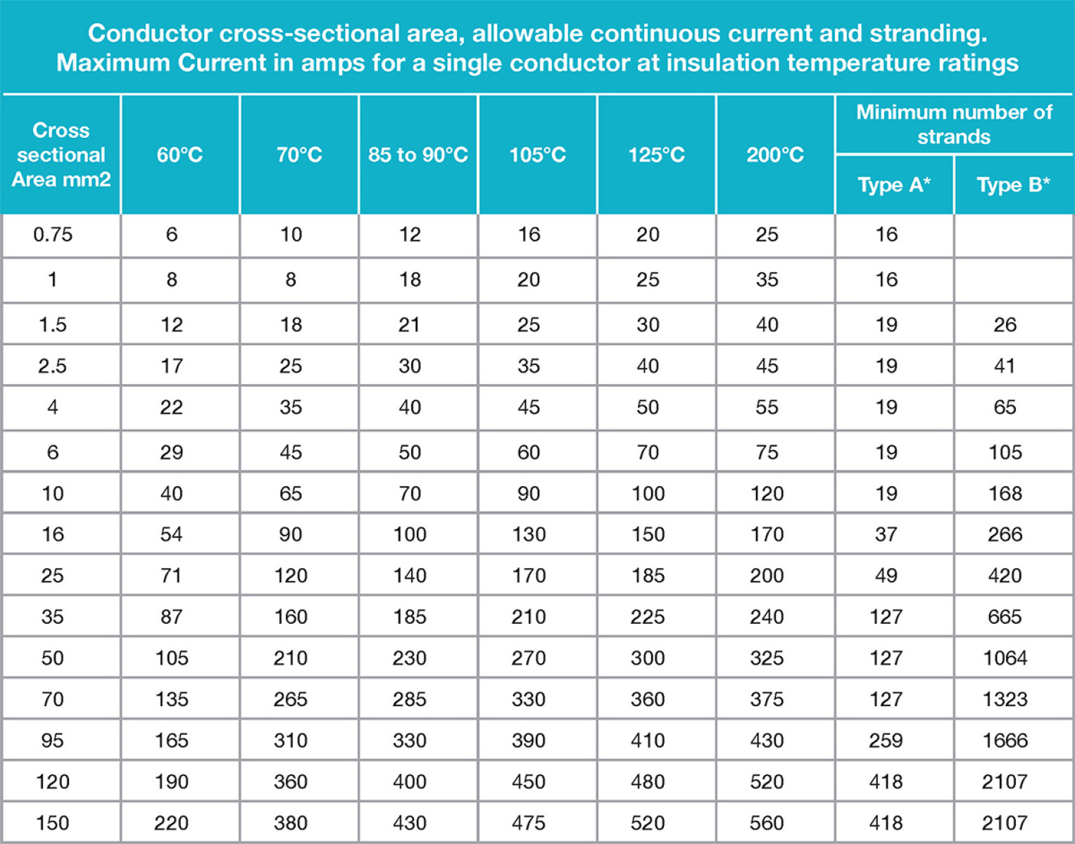
Notes:
Conductor current ratings may be interpolated for cross sectional areas between those shown in the Table.
* Conductors with at least a Type A stranding shall be used for general wiring of craft. Conductors with Type B stranding shall be used for any wiring where frequent flexing is involved during use.
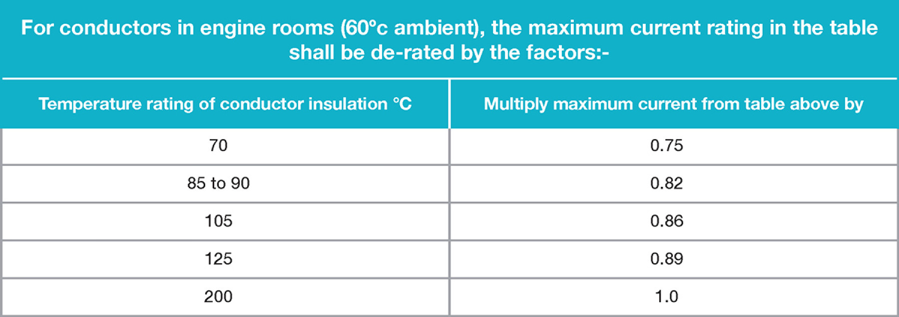
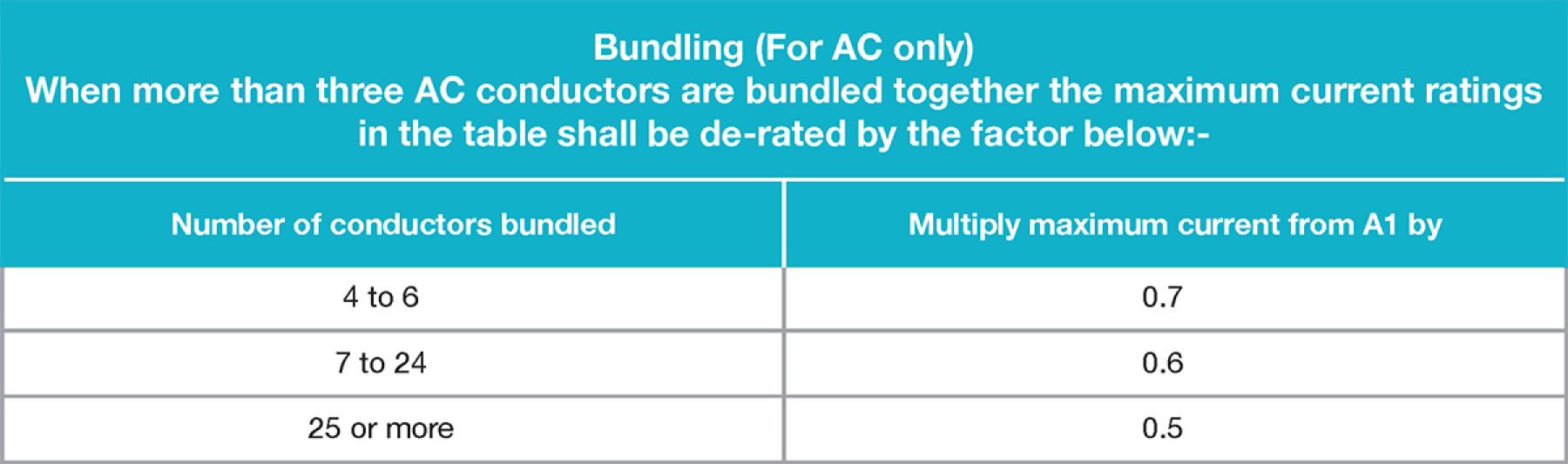
Notes:
De-rating reductions for temperature and building are cumulative where applicable. Bundling reduction factors are not normally considered necessary for DC cables in small craft.
Volt Drop Calculations
For information, (extra low voltage DC only) the volt drop on load may be calculated by using the following formula:

Where
E = Volts drop in volts
S = The conductor cross-section area in square millimetres
I = The load current in amperes
L = The total length, in metres, of conductor from the positive power source Connection to the electrical device and back to the negative source connection.
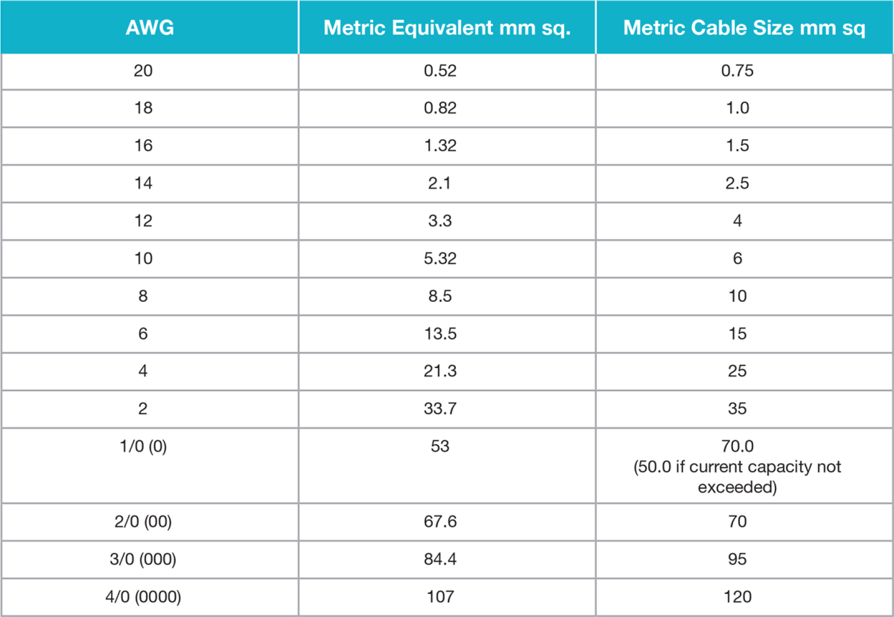
Metric Cable Size to AWG Conversion Tables
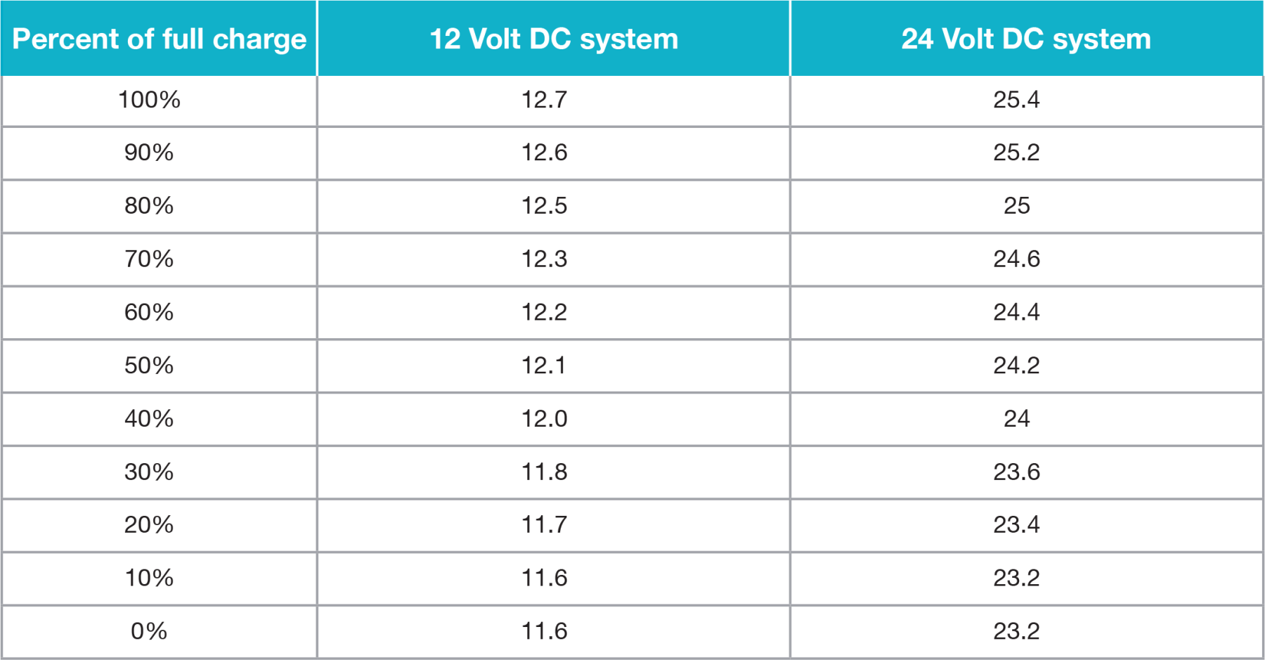
State of Charge
The following table will allow conversion of the readings obtained to an estimate of state of charge. The table is good for the batteries at 25 deg. C (77 deg F) that have been at rest for 3 hours or more. If the batteries are at a lower temperature you can expect lower voltage readings
Sign up to our mailing list
Keep up to date with the latest news and offers.

|
Thank you for Signing Up |

Submitting your details indicates that you have read and agree to our privacy policy and cookie policy. You can unsubscribe from our emails by using the link at the bottom of all emails we send.